Updated 28 Oct. 1999
Maybe You have seen the Delta conversion page. You cannot convert the digital decoders
(6080+6090), in the same degree as the Delta, because they do not use the 701.17 chip,
which is mandatory when you are upgrading/converting your decoders.
So what modifications CAN you make ?.
Remove the flickering in your lamps
This modification actually works on all decoders, also the Delta. There is no point in making this
modification if you already have made a delta add-on which removes the flicker (see the Delta page).
There are four types of modifications:
![]() Modification 1 : For the new
types of bulb-sockets, where the lampsocket has pins. (6080 and Delta ONLY !)
Modification 1 : For the new
types of bulb-sockets, where the lampsocket has pins. (6080 and Delta ONLY !)
![]() Modification 2 : For the new
types of bulb-sockets, where the lampsocket has pins.
Modification 2 : For the new
types of bulb-sockets, where the lampsocket has pins.
![]() Modification 3 : For the old
type where the bulb-socket is integrated with the chassis.(Primary
6090x)
Modification 3 : For the old
type where the bulb-socket is integrated with the chassis.(Primary
6090x)
![]() Modification 4 : For the new
types of bulb-sockets, where the lampsocket has pins. (6090x
ONLY !)
Modification 4 : For the new
types of bulb-sockets, where the lampsocket has pins. (6090x
ONLY !) ![]()
![]() You can retrofit some older locomotives with the
new type of bulb-sockets,
You can retrofit some older locomotives with the
new type of bulb-sockets,
- Check my tips & Tricks -page on how to do it.
If you have tried one of the modifications, and you're not satisfied with the result, you can try a
couple of things; check out the options!
Use Modification 1, if the decoder is a 6080 or Delta and you have the new types of bulb-sockets
with solder-pins on the back, or if you have the possibility to detach the bulb-socket from chassis.
So - what do you do ?
You actually only need one zener-diode ! . You simply connect one wire from the bulb to
the decoder, and the other wire through the zener-diode to motor-power - like this :

P.S you dont really need the zener diode - its only there for lowering
the voltage slightly - it has no other function
If this dosen´t remove the flicker to your satisfaction, you must go for Modification 2
Use Modification 2, if you have the new types of bulb-sockets with solder-pin on the back, or
if you have the possibility to detach the bulb-socket from chassis.
What do you do ?
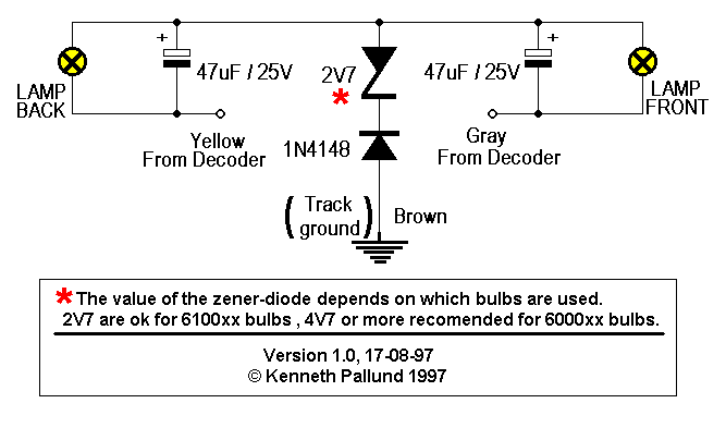
Well you only need 4 components; 1 Zener-diode, 1 normal diode, and 2 capacitors.
This is how you should connect them:

P.S you dont really need the zener diode - its only there for lowering
the voltage slightly - it has no other function
Not satisfied with the function of the modifications ? - try the options !.
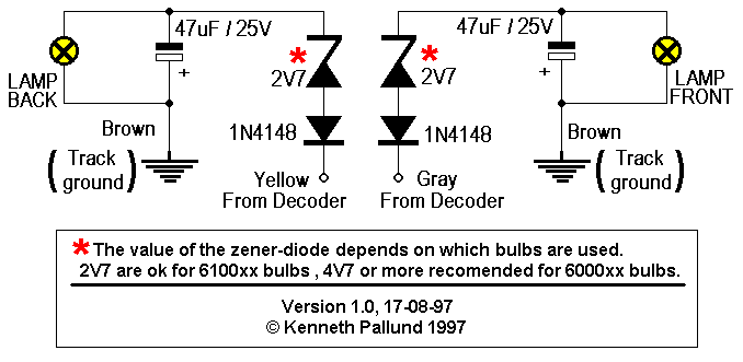
Use modification 3 if you have the old types of loc's where the bulb-socket is integrated with the
chassis.
What to do ?.
Here is what you need, and how you should connect it .

P.S you dont really need the zener diode - its only there for lowering
the voltage slightly - it has no other function
Not satisfied with the function of the modifications ? - try the options !.
Use Modification 4, if the decoder is a 6090 and you have the new types of bulb-sockets
with solder-pin on the back, or if you have the possibility to detach the bulb-socket from chassis.
If you look at modification 1, you will see that connecting the return-leads from the bulbs to where
the black wire is soldered, will remove the flicker. This is because the black wire "contains" stabilized
power, - its free from digital-signal noise. When it comes to the 6090, it does not use a black wire,
since it's a DC engine. That's why you normally have to use modification 2 or 3.
BUT ! - A clever/curious guy (Desmond Waterstone) has found a solder-pad on the 6090 PCB, which
have the same effect as the black wire - It removes the flicker !.
In honor of the finder the solder-pad was named "The Waterstone Terminal" !
What to do ?
Well - solder the yellow and gray wires to the bulbs, and their return leads to the
Waterstone Terminal - simple and effective.
If you feel that the bulbs burn to bright you can insert a diode or a zener-diode in the leads to the
solder-pad. If you use a Zener-diode, it should have its cathode(marked with a band) connected to the
pad. If you will use a normal diode it should have its anode connected to the solder-pad.
Connection :

If you are converting a loc, from analog to digital, and the loc originally was fitted with an electronic
circuit to prevent the loc from jumping when you change direction, it is most likely, that the bulbs are
LOW VOLTAGE bulbs. These bulbs will burn VERY brightly, and they may burn out fast. If you
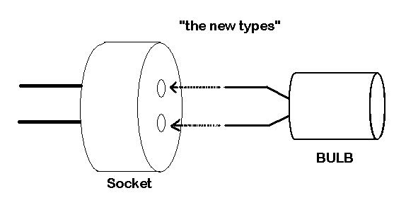
think they burn to brightly you could change the bulbs to 6100xx. This issue is typically a factor
when you are dealing with the new bulb-sockets, which uses these new type of bulbs:

The options ==> (only for modifications 1 - 3) <==
1. If the lamps still flickers, try to increase the value of capacitor. (eg. x 2 or x3 or more)
2. If you think the capacitors are/gets to big, try using tantalum capacitors.
3. If the light is too bright, increase the value of the Zener-diode.
4. If the light from lamps are not bright enough, lower the value of the Zener-diode or remove it.