
Updated 27 Sep. 2002
The Delta Decoder is Märklin's cheapest decoder, and the one with the fewest functions.
However this can be changed, with some additional components and a solder iron.
So what can you do yourself, to make the Delta Decoder better.
Check it out:
Get all 80 addresses. (This modification can be performed on all Delta decoders)
When you use the dip switch ![]() you can either set ON or OFF(pretty obvious)
you can either set ON or OFF(pretty obvious)
"ON" matches the odd number on the 6080/6090, and "OFF" matches "--" that is neither
odd or even numbers are set to ON on the 6080/6090 dip switch.
In order to chose a digital address look at the digital address table, and find your desired
address.
On the Delta decoder you have odd numbers and "open", therefore the problem is to get
the even numbers. What you do is set the switch OFF, and then solder a wire to a reference-
point, which gives you level for the even numbers. You therefore need to solder the wire from the
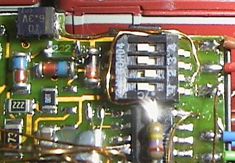
Delta dip switch to eg. the "big"
capacitor. 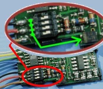
Say you want to make the setting of dip3 to equal the
level for an even number, you solder a wire from dip3,
on the side that faces the board edge, to the capacitor,
and solder the wire onto the side of the capacitor which
has a marking (a light or dark line, depending on the color
of the capacitor).
If you want to use eg. address 64, the digital setting is:
| Märklin setting | 6080/6090 Dip switch setting |
| -2 3- -6 -- | set the following: ON : 2, 3, 6 OFF: 1,4,5,7,8 |
Dip1 on the Delta equals dip1+2 on the digital. Dip2 equals dip3+4 and so on.
In digital, you use two switches, to make one bit. It can either be high, low, or "floating"
(both switches=off).
Look in this table, to see the possible settings:
| DIP "odd" | DIP "even" | Result | |
| on | on | illegal | |
| on | off | low | |
| off | on | high | |
| off | off | floating |
* This is the setting that needs the modification. You set the switch to "OFF" and solder
a wire to the capacitor.
So, in the case of address 64 you set the Delta switch 1:OFF 2:ON 3:OFF 4:OFF
You then solder wires from dip1 and dip3 to the capacitor.
Just remember : YOU MUST NEVER SET THE SWITCH TO "ON" AND SOLDER
A WIRE TO THE CAPACITOR, THIS WILL RESULT IN A SHORTCIRCUIT ! .
![]() Examples:
Examples:
This is how you make address 03 ( ON, OFF+solder+off, ON, ON )
This is how you make address 63 ( ON, ON, OFF+solder, OFF )
If you don't want to modify you Delta decoder, you are limited to these addresses.
So maybe it's worth taking the chance.
If you want to read more about the digital format, or how Märklins trinary format
Works, try this excellent page New Märklin Motorola Format by Andrea Scorzoni.
| Get the function. | This modification can ONLY be performed on 701.17-based Delta decoders. |
The function equals the button "function" on your Control Unit 6021. This function is already
present on the 6080 and 6090. You use it to turn on/off the headlights or to drive a Telex or a
smoke unit. To have this function on your Delta decoder you need to solder a bit, and cut a little
in your Delta circuit board. How much depend on which model of decoder you have. What you need
is actually only two 10K(can be smaller) resistors and maybe a 2V7 zenerdiode.
(maybe also 2 transistors if you have one of the old decoders). Besides adding the function it can
also remove the annoying flickering you normally se in your train's headlights.
The Function
The Function is enabled, by adding the components described in the schematics
You may have to cut a few leads on the Delta Circuit board, solder the appropriate components,
and connect your bulbs, Telex or smoke unit, and you have the function.
BUT - how do you go about making the conversion.
There are two ways:
1. You use a sharp knife to cut/break the leads that comes from the 701.17 chip. You then solder the
resistors where you find it best. The disadvantages with this method is : where should I cut ?
and what if I regret the conversion ?. (the questions are rhetorical and need no answer)
2. The second method is the one I personally use. It is a bit more difficult, but a far better solution,
because you don't have to cut at all, so you can always return to the starting point.
First of all you need to buy two SMD 10Kohm resistors.(actually any value from 1 - 10 Kohm will do !)
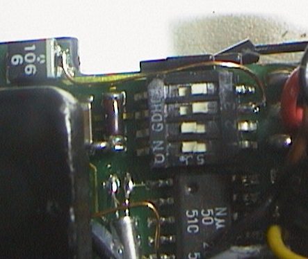
You then have to raise pin 6 and 7 on the 701.17 chip, from the circuit board. Use the tip of a small
screwdriver, which you insert between two pins on the chip. You then apply heat (with a soldering iron)
and gently tweak the pin up, as shown in this drawing.
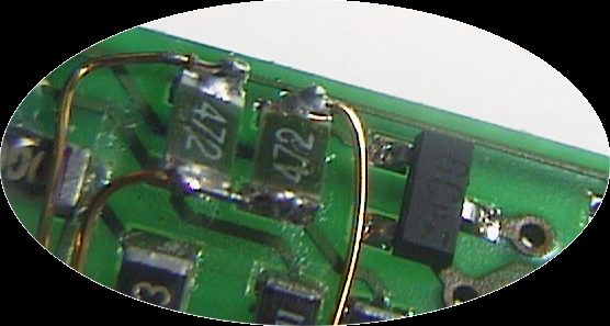
Next step are the resistors. Desolder the two resistors, shown on this
picture.(this is only valid for the decoders where the resistors are placed as shown).
Now you solder the the two (1-)10k resistors to the board. Here is another tricky task, because the resistors
should be soldered at angle, and they should be soldered to the plates nearest the board's edge.
Check the pictures/drawings for details (sorry, the pictures are not totally clear)
How should you angle the resistors, compared to a normally soldered resistor ?
How should it look ? Example 1 Example 2
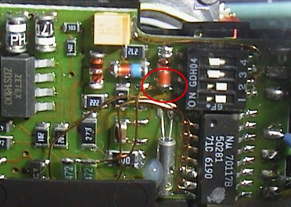
Then you solder the wires. I use thin lacquer-isolated copper wire. You solder wires from the raised
pins on chip to the plates where you soldered the resistors - see this example. The "top"-ends of the
resistors should be soldered together and then connected to the diode right beside the dip-switch.
The other wires should be soldered to the plates where the resistors are soldered to the board. The wires
are then to be connected to pin6 and 7 on the 701.17 chip.
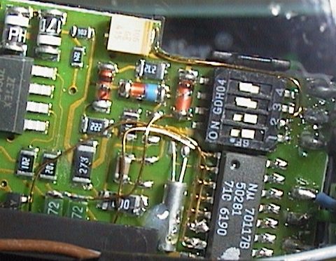
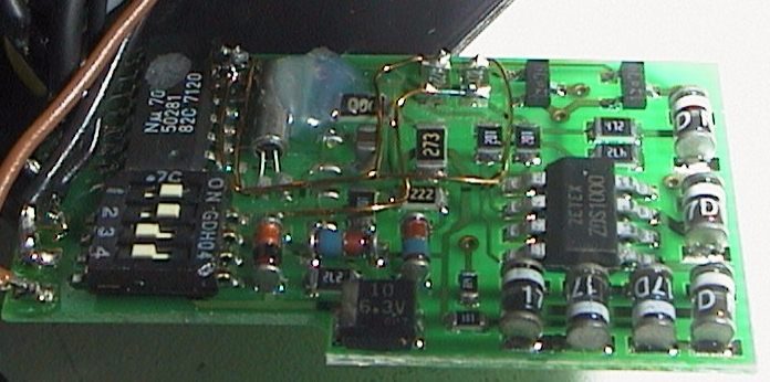
Here are some pictures showing the above descriptions
![]() The raised chip-pins,
with wires soldered
The raised chip-pins,
with wires soldered
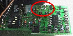
![]() Overview of the
finished result
Overview of the
finished result
Flickering
You can only remove the flickering, if your bulb sockets are of the new type with two solder
pins on the back, or you have the possibility to detach the bulb from the chassis(on old loc's
the bulb-holder is normally integrated in the chassis, so here it is difficult).
(Check my tips & Tricks -page on how to retrofit a locomotive with the new type of bulb-sockets)
You connect the bulbs with one wire to the transistor(the yellow and gray wires) on your Delta
and the other wire through the zener to motor power.(normally the black wire)
Voila ! No more Flicker in your light bulbs.
It's all described on schematics you can download. If you have the older types, and you cannot
detach the socket from the chassis, you can still remove flicker, but you must make the modification
with extra components. Check out the digital enhancement page.
You don't HAVE to use the Zenerdiodes which you see in the schematics. Their job is to lower the
voltage to the bulbs, because the Digital voltage is higher than the normal analog voltage. If you
are satisfied with the bulbs brightness, don't add the zenerdiodes.
P.S If you are converting a loc which have an electronic circuit to change direction, it is most
likely that the bulbs are Märklin number 6000xx. These bulbs are LOW VOLTAGE bulbs, and
will burn VERY brightly, and they may burn out fast. You should change the bulbs to 6100xx.
The schematics is made by Dr Michael König Who also has an excellent homepage regarding this subject
Get the four extra functions. This modification can ONLY be performed on 701.17-based decoders
It is now possible to enable all the four function you see on your Control Unit (F1-F4), as well
as the "normal" function, described in a earlier paragraph. You can also avoid flickering, just
connect your bulbs(possibly through a zenerdiode, to lower the voltage) to motor-power instead
off chassis(track ground).
This conversion is not as easy , as the others. First up, you need a few extra components, and
connect them acording to the schematic shown here to the right. (Schematic created by Michael könig)
You use a 4094 shift register and four transistors.
The transistors must be connected to the output of the 4094.
The transistors handling the light front and back, should be able
to handle 200mA.The transistors who handle the function output
should handle approximately. 1A.
And last, you will also need a 270Kohm resistor.
Bo braendstrup has made a very small PCB, which uses SMT-
components. He uses a dual transistor ;NDC7002N for the
normal functions(the front/back lights). And two ZETEX
FMMT491A to handle the function output. In this version only
F1 and F2 are enabled, but it is possible to enable all four functions. But here you are on your own.
You have to build the add-on yourself, according to the schematic above. This however requires at bit
more work, than just connecting a premade curcuitboard.
Here are Bo Braendstrup's PCB layout
enlarged :
R1+R2 : 820 Ohm
Q1+Q3 : FMMT491A
Q2 : NDC7002N
IC1 : CMOS 4094
Actual size is 1,4 cm x 1,4 cm
The assembly:
First the hard part. You need to desolder pin 3,4,5,6,7 on the 701.17 chip from the PCB.
I find the easiest way, is to use a small screwdriver. You place it between two pins eg 2 and 3.
You then put your solder iron down on pin 3 and at same time use your screwdriver to
gently tweak pin 3 up from the PCB.
You then solder wires from the add-on to the pins you desolderd on the Delta chip. Look at the
schematic to see what pins to connect with each other. Finally you mount the 270Kohm
resistor between Delta chip pin 5 to track ground (brown wire). It is not totally nessesary to use
all the 22 Kohm resistors, as shown in the schematic -you can chose not to use them.
You can read more about this subject on Dr. König's homepage and Bo Braendstrup's homepage.
Bo has a great homepage with allot of modifications to Märklin's Digital system.